
Circuit Troubleshooting 101 (Part 1 )
7 years ago
A typical problem: the end of the day, soldering is done, but the module doesn't work. What to do? In this multipart series I want to show various methods every DIY synthesizer enthusiast can use to figure out why a particular module or kit doesn't work. This is mostly aimed at Eurorack modules which have a power supply of ±12V, but parts of this could be adapted to other synthesizers as well (±15V, Single Supply).
The most important thing is don't panic. Try to systematically resolve the issue. If a human created that thing it can also be understood by a human. If it doesn't work, there is a reason. Finding this reason can be hard, but it is possible. The method is quite simple – if you can't solve the problem spontaneously you have to BREAK IT DOWN INTO SMALLER, MANAGABLE PARTS. That means instead of understanding everything at once, try to focus on the things you can understand first and make sure they work.
Before powering on a module
There are some things you should always consider doing before connecting and powering on a module. If you already powered the module on and it doesn't work, it still makes sense to do these things just to be sure.
[0] Measure the Power Cable connectivity
The first point of failure is the power cable.
For this you should use your multimeter in continuity testing mode. This mode is usually a sub-mode of resistance measuring mode (usually denoted by the greek letter Ω) and is often marked with a sound wave symbol (🔊), because the multimeter will beep when to parts are connected via wire/trace. Switch your multimeter to continuity testing mode and let the two test leads touch – if it beeps you are good.
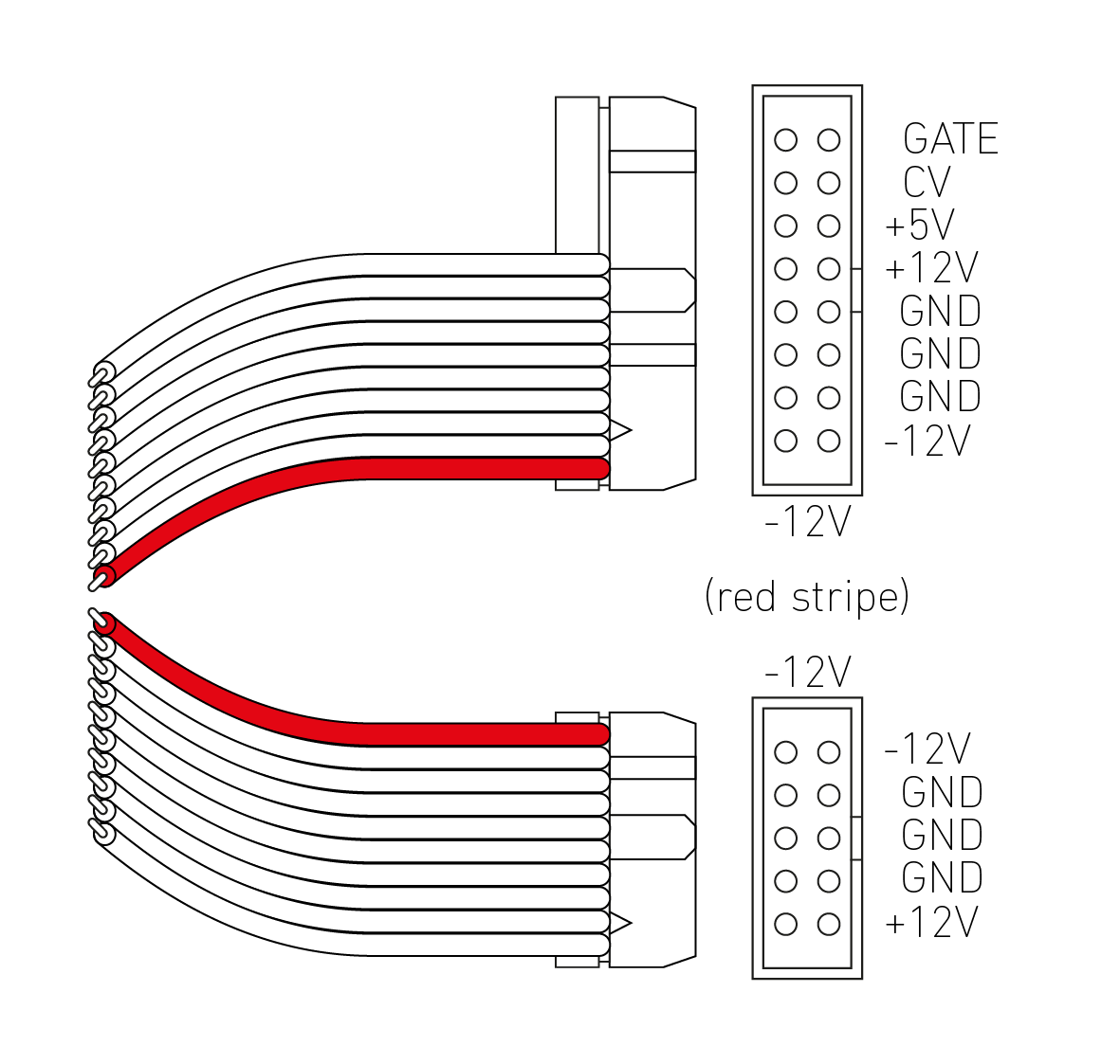
First make sure your powercable looks like this. Especially pay attention to the orientation of the red stripe and the "nose" of each connector. If it doesn't match up, you either made a mistake when building the cable, or the manufacturer who made it uses a different standard (in that case ask them if this is intentional).
To verify your power cable is working you basically test if all things that should be connected ARE connected and if all things that shouldn't be connected ARE NOT connected. Because the tips of the test lead of a multimeter are usually to wide to fit into the holes of such a connector it can make sense to use pieces of wire or the trimmed legs of a resistor to measure these connections.
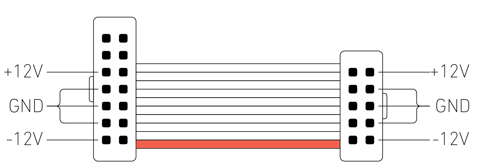
This means:
+12Vholes should only be connected to each other-12Vholes should only be connected to each otherGNDholes should only be connected to each other
Note: not every e.g. GND hole will be connected to every other GND hole, but it should be connected at least once
If you are sure everything that should beep beeps, and everything that shouldn't beep stays silent, you can:
- switch your multimeter to Voltage mode
- plug your power cable (without module!) into the busboard
- switch on the power to of your rack
- measure between
GND(black test lead) and+12V(red test lead) – this should read close to +12V - measure between
GND(black test lead) and-12V(red test lead) – this should read close to -12V
Now you can be sure your powercable delivers the right kind of voltage on the right pin – you can rule this one out as a source of error. As a nice side effect you now also know your busboard and your power supply are alright.
[1] Make sure the voltages end up where they should
Most modules use some sort of stripe or a "-12V" print to indicate where the red strip of your powercable should point to. Some manufacturers use a bridge rectifier to alow you to plug the cable "either way", but it will usually say so on the board. If your board doesn't have such a feature, connecting the power the wrong way around could either destroy it, or (if it has some sort of reverse polarity protection) wouldn't work.
A good indicator to find where +12V or -12V is to look at polarized capacitors. These capacitors are polarized, that means they have a positive and a negative side, like a regular battery.
In a simplified schematic this might look a little like this, with C1 and C2 as polarized capacitors:
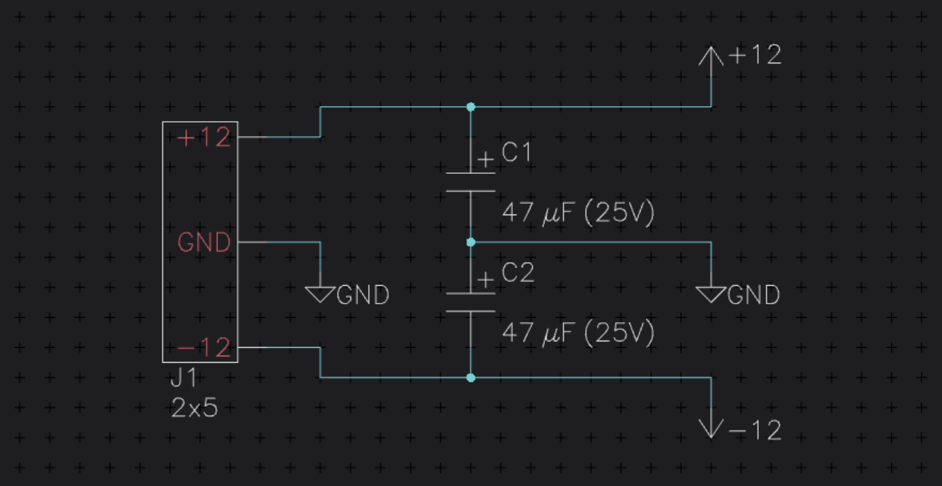
As you can see the positive side of C1 is connected to +12 while the negative side is connected to GND. For C2 it is opposite: the positive side is connected to GND while the negative side is connected to -12. This is because from the perspective of C2 the 0V at GND are more positive than the -12V.
On a board this thing would look similar to this:
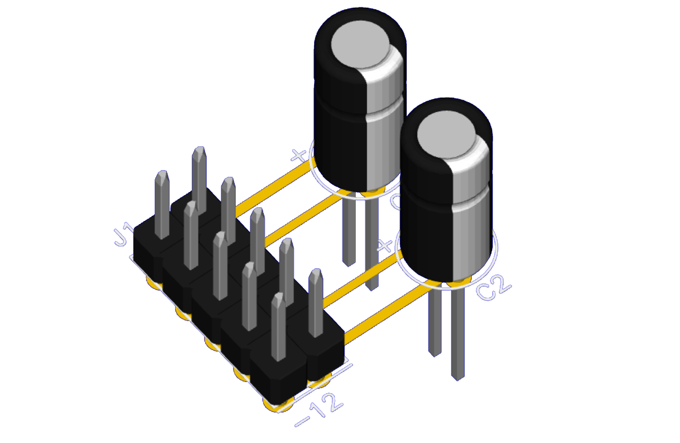
The stripe on a polarized (electrolytic) capacitor denotes the negative side of the capacitor. On a real board the traces would be coated with paint, but we can clearly see which side of the connector is connected to the white stripe of the capacitor – this side is the negative side. It is very likely that in a real world circuit there are parts between the polarized capacitor and the connector, sometimes diodes (for reverse polarity protection), sometimes ferrite beads (for HF suppression), sometimes a resistor (for crude current limiting), or a combination of these.
However, if you are sure you got the polarity right, you can rule out another issue.
[2] Measure the module for short circuits
If you can remove your ICs (if they are in a socket), you should do so now. Again take your multimeter and switch it to resistance measure mode (Ω). Measure the resistance between any of the GND pins and any of the +12V and -12V pins of the power connector (obviously with no power applied). If this is smaller than a few megaohms (MΩ), something might be wrong. If it is bellw one Kilohm (kΩ), you have a short circuit somewhere (this means something directly connects your rails (±12V) to GND).
[3] Measure the module IC power pins
If you had no short circuit in step 2, switch the multimeter to voltage mode (V) and connect your module (again without ICs) to the busboard, using your checked power cable. These are the positive and negative power pins of the IC. The idea now is to measure the voltage difference between GND and the ICs power pins. This means we put the black measuring lead to GND (e.g. at the middle pins of our power connector) and the red lead to the according spot in the IC socket. To find this spot we need to take a look at the ICs datasheet. If you have an TL072 for example, just google for "TL072 datasheet" and open the first PDF. Somewhere in there there will be a graphic similar to this one:
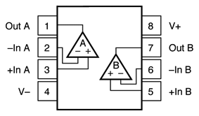
The pins we are interested in are the V- and the V+ pins. Sometimes V- will also be called GND, COM, Vee or so, while V+ is sometimes called Vpp. If we were to measure the voltage between GND and V+ and we get something close to +12V (or sometimes 10V or so), we are fine. For V- we should get the same thing but with a negative polarity. If this is swapped, maybe you placed your IC in the wrong way? If there is no power, but there is power at the power connector, there must be something wrong inbetween.
Conclusion
Making sure the right power voltage arrives where it should, without going anywhere else is already a very good start. By systematically breaking a big problem into smaller pieces it gets managable and even if we are not experts or the circuit is unknown to us, we can get ideas about where the error could be from what we see. This is the first part, I will discuss additional steps in the next part.